
Technical requirements for electronic control gears for LED and fluorescent luminaires
562 KB

LED is pervading all areas of lighting technology – from torches to headlights, in offices, industry and outdoors. Continuous improvement, better quality and lower prices for the light emitting diodes are causing the share of luminaires equipped with LED lamps to soar.
As a result, the number of LED lights used, not just for general lighting, but also as safety luminaires, is growing rapidly. Operating general lighting from central power systems does, however, require careful consideration and meticulous advance planning. Don't be fooled by labels claiming the lights are "suitable for emergency lighting" – they do not automatically imply compatibility with the central power systems in use.
Most emergency lighting manufacturers offer switch and monitoring modules for connecting third-party luminaires to central power systems. During a mains failure or function testing, these modules switch the luminaires on and monitor the connected load. If a lamp is defective, the monitoring module reports a luminaire fault to the central power system.
At least in theory. In practice, however, the luminaires or inbuilt drivers need to satisfy certain criteria if fault detection is to be reliable.
If third-party luminaires are to be operated from central power systems, the LED drivers must be suitable, not just for operation at 230V AC voltage ±10% 50Hz; they must also operate reliably at 186V – 260V DC battery voltage.
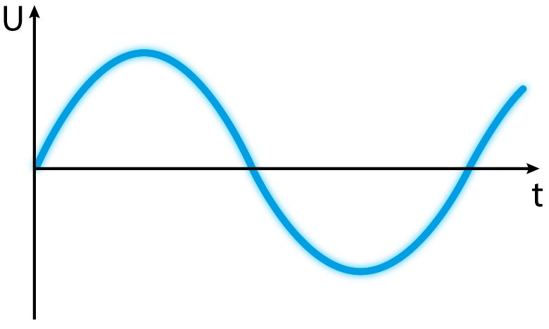
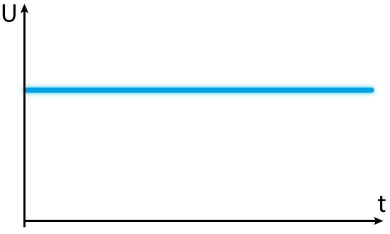
Mixed operation systems that permit operation of luminaires in maintained, non-maintained or switched maintained mode within a single circuit must switch all of the luminaires on in test and emergency operation mode. To ensure the non-maintained lights and switched safety luminaires are also switched on in such instances, the type of voltage or sinewave (phase angle control, pulsating DC voltage, etc.) is generally modified. When connecting third-party luminaires, therefore, care must be taken to ensure the inbuilt LED drivers can also be operated at the modified voltages. Otherwise, if the worst comes to the worst, the modified general luminaire may not switch on during emergency operation.
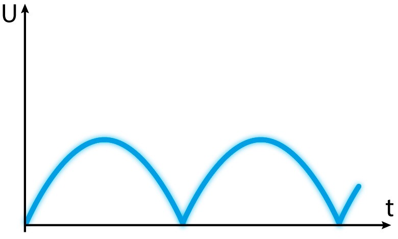
In order to supply and switch emergency exit and safety luminaires in the modes described above in one and the same circuit, INOTEC central power systems use patented JOKER technology – a pulsating DC voltage (see illustration detailing types of voltage).
To ensure compliance with statutory switchover time requirements, central power systems must switch over from mains to battery or from AC to DC voltage within one second in emergency operation. Once mains power has been restored, switchover from DC back to AC voltage must be accomplished within the same space of time. Some LED drivers with microcontrollers have problems with switchover times of less than one second. Microcontrollers have been known to freeze sporadically and not switch the luminaires on during test operation or in an emergency.
When planning and sizing central power systems, the maximum current consumption per circuit needs to be taken into consideration. To do this, the current consumption of each individual luminaire must be measured in AC operation.
Since central power systems use contactors and relays with limited current carrying capacity to switch between mains and substitute power source, the inrush currents of the connected luminaires must also be calculated. The measuring procedure is, however, not standardized, and different approaches result in discrepancies.
If the inrush currents are too high, they can damage the central power system and inbuilt components.
Modules that monitor individual luminaires monitor the current consumption on the primary side of the LED driver. During function testing (battery operation/DC), all of the connected luminaires are switched on, and the monitoring modules measure their current consumption. Defined thresholds are used to assess the results. If the upper threshold is exceeded, the monitoring module reports back to the central power system that everything is OK. If the measurement is below the lower threshold, the central power system signals a luminaire fault.
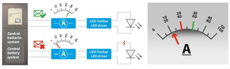
In order to select the right monitoring module, the input current of the LED driver must be measured in DC operation (186V–260V DC) with LED module connected. The smallest measurement must be above the threshold for OK confirmation.
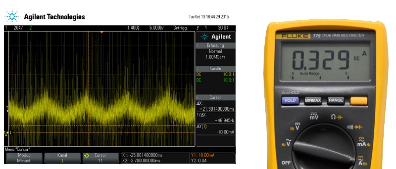
Using the wrong measuring equipment can quickly result in misinterpretation. Some of the LED drivers in the marketplace exhibit "pulsed" current consumption on the primary side, which normal multimeters or ammeters cannot detect as such, as they often measure the mean value. In such cases, the current consumption at the time of measurement by the monitoring module may be below the fault threshold although the multimeter measurement of the current should be above this level. As a result, luminaires occasionally signal a fault during function testing although the lamp is fine.
In the example below, the current consumption of the LED driver was measured with a multimeter and an oscilloscope.
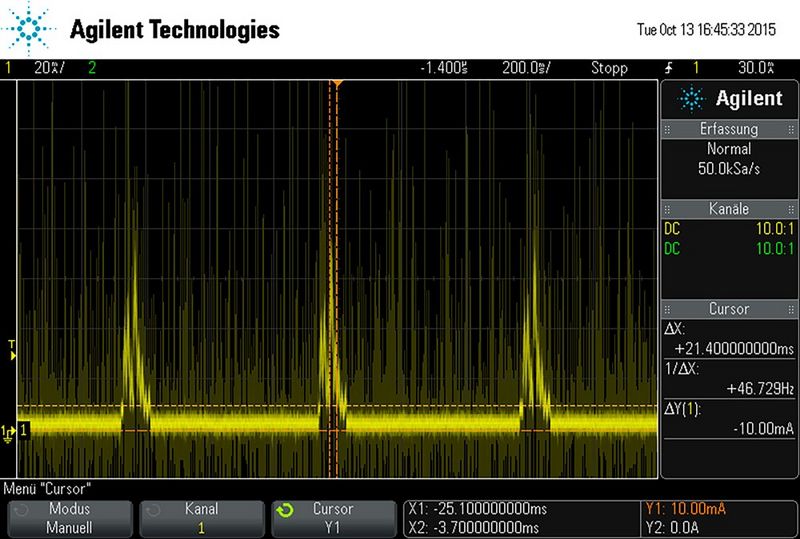
In order to simulate a fault, the current consumption of the LED driver is measured when the lamp is not connected. When monitoring third-party luminaires, only the failure of the entire lamp is observed. It is not possible to detect if individual LEDs or LED strings have failed.
The right measuring equipment is also important when measuring residual current. Studies of numerous LED drivers from various manufacturers revealed that current consumption is not constant in some drivers if the lamp is defective. The picture below shows an oscillogram tracking the current consumption of a driver without connected lamp. The driver attempts to switch the lamp on again at frequent intervals, and, in doing so, generates a current pulse. If the monitoring module performs its measurement during this pulse, it may report back that the lamp is OK although it is actually faulty.
Most DALI drivers are programmed to reduce luminous flux by a fixed amount in DC operation (usually preset to 15%). If the LED driver detects DC voltage input, the luminaire switches on and dims to the preset "DC level". While in DC operation, the driver no longer responds to commands from the DALI controller. This reduction in luminous flux must be taken into account, especially when planning enhanced illuminance requirements, e.g. sports facilities, high-risk work areas, etc. Manufacturers can preset the DC level on a driver with appropriate hardware and software.
As reduced luminous flux is accompanied by reduced current consumption, this must be coordinated with the manufacturer of the luminaire or driver in advance when measuring current consumption.
Compatibility with the relevant types of voltage must be tested to ensure secure operation of DALI drivers on central power systems. If the DALI driver misinterprets the applied voltage, it may switch back and forth between normal operation and DC level: creating the impression of flickering lights.
Some manufacturers of emergency lights offer special DALI monitoring modules to assure separate control of the general and safety lighting. The modules interrupt the DALI BUS and take over the control of the luminaire. To do this, the manufacturer must first have deactivated the DC level function. The lamp is monitored by checking the fault memory in the DALI driver. Correct monitoring cannot be guaranteed in such cases.
In order to guarantee the safety of emergency lighting systems coupled with BUS controlled luminaires, the luminaires must switch to secure operation if the BUS malfunctions (interruption, short circuit). In practice, not every control gear has proven to support this function. In some cases, the function had to be activated in the control gear.
Installing monitoring modules in general lighting constitutes a structural modification of the luminaire. As a result, any test marks, CE marks and EU declarations of conformity become invalid.
Whoever modifies a luminaire becomes a manufacturer in the eyes of the law – with all associated obligations. They must, for example, attach a new type label and CE mark, and must issue a new EU declaration of conformity. In doing so, they guarantee compliance with all legal directives, such as the Low Voltage, EMC and RoHS Directives, and all associated standards.
Most general lighting manufacturers build different drivers into the same luminaire model, depending on availability. If the LED driver changes, the interaction of the luminaire with the emergency lighting must be retested. Care must therefore be taken to ensure that the same tested drivers are used for deliveries, subsequent deliveries or spare parts deliveries. Added to which, new LED lamps – supplied as spares, for example – can influence luminaire performance and thus monitoring performance.
Improvements and changes to LED drivers over their life cycle are not always recognizable. Small changes to the hardware or software may result in previously tested drivers no longer being compatible with the central power systems. Since not every alteration is communicated accordingly, only the manufacturer of the driver can guarantee compatibility.
Mixing general lighting with safety lighting can produce all sorts of different compatibility issues. The manufacturer of the driver or luminaire must test and approve flawless operation in advance. Remedying the problems described above – which are all caused by insufficient planning, modifications of LED drivers or incorrect measuring procedures – is costly and time consuming for everyone involved.
To ensure compliance with legal regulations, we recommend commissioning the general lighting manufacturer to install the switch and monitoring modules. They have the technical means to perform the required measurements.
Separate safety luminaires provided by the manufacturer of the central power system should be used alongside the general lighting to ensure flawless functioning and the aim of protection. That is the only way we – as manufacturers of emergency lighting systems – can guarantee reliable operation.
| LED driver properties | Fault | Effect |
|---|---|---|
| Pulsating inrush current on the LED driver | The current measured during function testing may be below the OK threshold. | A luminaire malfunction is reported although the lamp is OK. |
| Inrush peaks when lamp is faulty | The current measured during function testing may be above the threshold for luminaire malfunctions. | A faulty lamp may not be detected. |
| LED driver not compatible with the switchover time | The microcontroller freezes during operation. | The luminaires do not switch on in an emergency. |
| Inaccurately measured luminaire inrush current | The permissible inrush current for a monitoring module or circuit may be exceeded. | This may damage the components. |
| Dimming level during DC operation of LED drivers has been ignored during planning |
| A luminaire malfunction is reported although the lamp is OK. Luminaire behaviour in DC mode must be reprogrammed. |
| DALI driver does not report lamp fault | The error bit is not correctly transmitted to the DALI monitoring module. | Luminaire malfunction is not detected. |
| DALI driver misinterprets the type of voltage | The DALI drivers switches back and forth between normal operation and DC level. | Luminaires dim up and down. Driver must be replaced or DC level adjusted. |
| DALI driver does not respond to BUS malfunction | Failure to meet DALI requirements. | Luminaire does not switch on reliably when BUS is malfunctioning. |
This table was derived from problems witnessed in practice with various makes of LED drivers.