Dynamic escape routing as a compensatory measure
Fire safety requirements are fulfilled even in exceptional cases
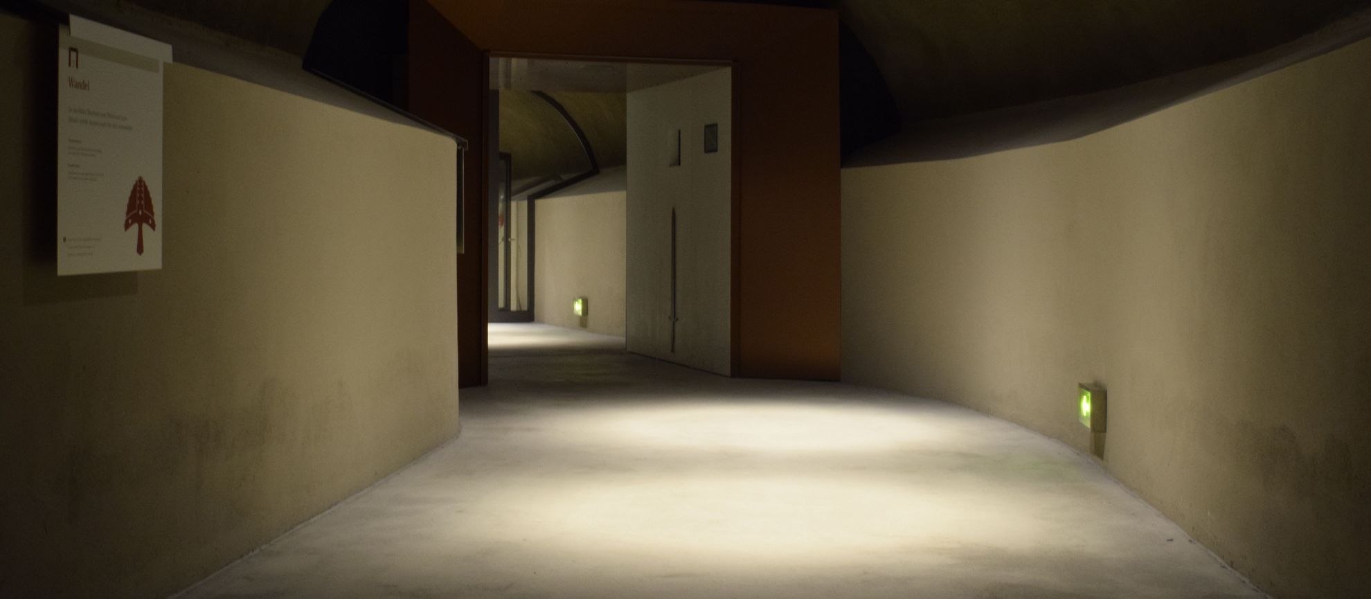
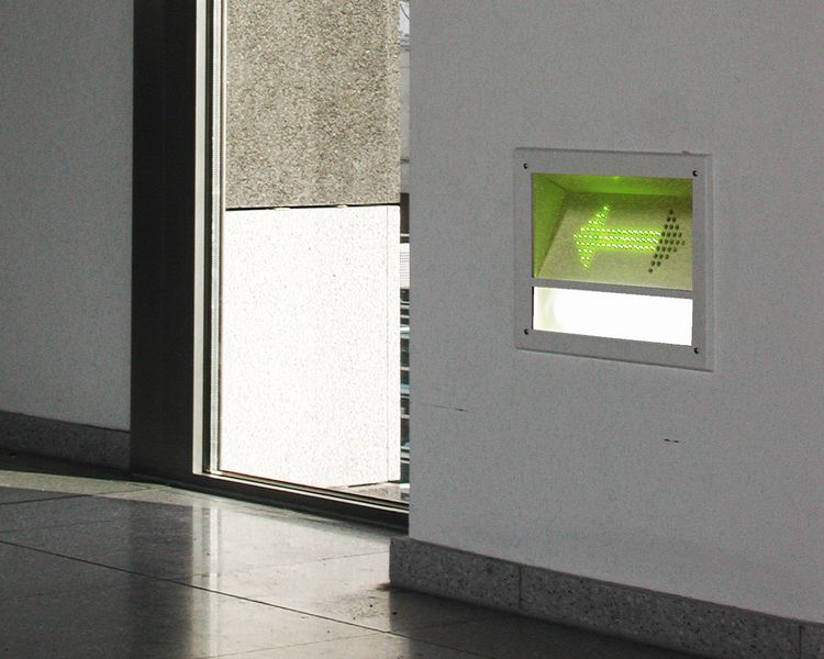
If a fire occurs, the greatest danger lies in the smoke, which can quickly spread through the building. It rises to the ceiling, collects there and makes safety lighting and escape route signage ineffective. In such cases, the only thing that allows people to find their way out is low-location lighting and signage. A dynamic escape routing system can do both.
However, optical dynamic escape routing is essentially only an addition to conventional emergency and safety lighting, and cannot replace the latter. In the event of a power cut, safety lighting connected to an automatically triggered power supply for safety systems ensures the illumination of specific areas (escape routes, assembly rooms, etc.) with a specified illuminance. It is also responsible for lighting or backlighting emergency exit luminaires and direction signs signposting an escape route. However, this signage cannot react to danger by altering the direction sign. On the contrary, it can point in the wrong direction, in other words into the danger zone.
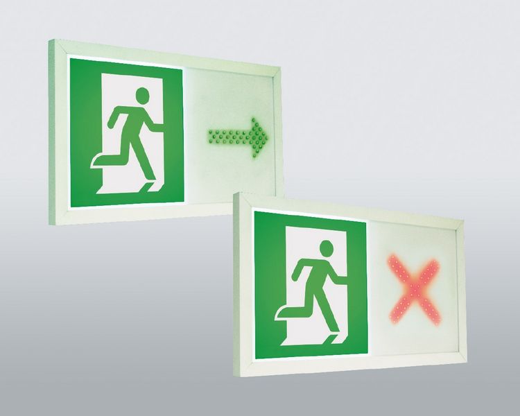
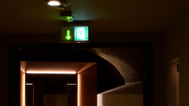
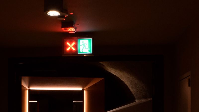
In such cases, dynamic escape routing is helpful. It is controlled by a fire alarm system. Emergency exit luminaires with a variable indication of direction visually close off the affected areas and indicate alternative escape directions. For people inside a smoke-filled area, low-location luminaires with direction signage offer the necessary lighting and way guidance for them to be able to leave the affected area by the shortest route.
Application fields for dynamic escape routing systems
The technical rules for workplaces (ASR) stipulate in which cases a dynamic escape routing system is to be used. This is the case where a heightened risk exists because of local or operational conditions – for example, in large interconnecting or multi-storey building complexes, where a high number of the persons present are not familiar with the surroundings or where a high number of persons present have limited mobility. Such circumstances may require a safety guidance system that responds to any danger and indicates the best escape route (extract from ASR A2.3 of August 2007). In addition, a dynamic escape routing system can be employed as a compensatory measure where there are deviations from the building code.
Dynamic escape routing as a compensatory measure
Dynamic escape routing can be employed as a compensatory measure in new builds, building renovations or even in classified heritage buildings, where there are deviations from the building code.
Building code fire safety requirements are sometimes difficult if not impossible to meet when renovating historical buildings, in particular. Solutions then have to be found that retain the unique characteristics of historical buildings but at the same time are compliant with both modern-day fire safety demands and heritage protection requirements. Compromise is frequently necessary when juggling regulations and heritage protection requirements, and compensatory measures have to be found that are compliant with the safety objective of enabling people to rescue themselves.
The creativity of property owners, architects and specialist fire safety planners is also often curtailed by building code fire safety requirements when planning new builds, special constructions or special-purpose structures, renovations or conversions. They will want to take into account architectural considerations, such as transparency, functionality and aesthetics, but this is only possible to a limited extent if they are also to comply strictly with the legal regulations. It is only possible to implement the building plans by incorporating technical measures to compensate for deviations from the regulations. The use of dynamic escape routing can introduce more freedom of action and flexibility when designing a building, as experience has often shown.
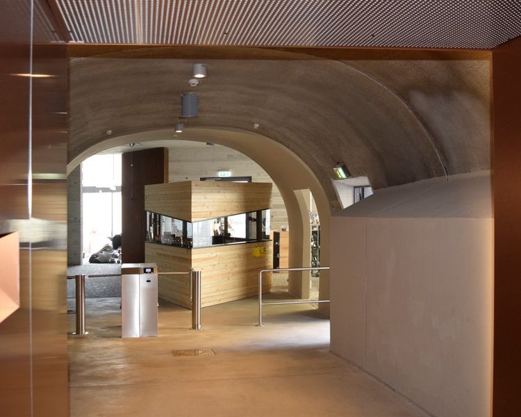
Case study: Pedestrian tunnel in Altena
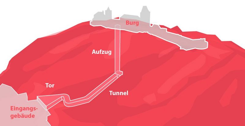
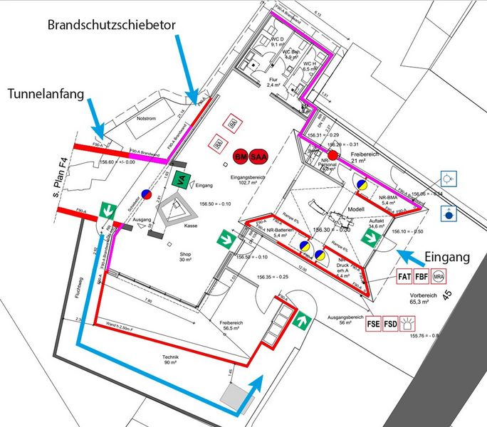
The town of Altena, in North Rhine-Westphalia, was planning to build a pedestrian tunnel with lift to provide access to Altena Castle. The entrance building leading to the tunnel is located in the town and is reached across a public traffic area. The tunnel is around 93 m long, with a lift at the end to take visitors up to the castle.
In normal operation, the tunnel is accessed from the entrance building in front of it. In order to create an escape route out of the tunnel, and access for the fire service, that was separate from the entrance building, a bypass was included in the plans. It sits between the entrance building and the tunnel, and leads directly into the open. The tunnel's length of over 90 m exceeds the 35-m length permissible for escape routes under German building regulation § 37 BauO NRW by over 55 metres. As such, the building code-specified safety objective of ensuring an escape route is a central function of the construction. Furthermore, the construction does not have a second escape route, which constitutes a deviation from building regulation § 17 (3) BauO NRW.
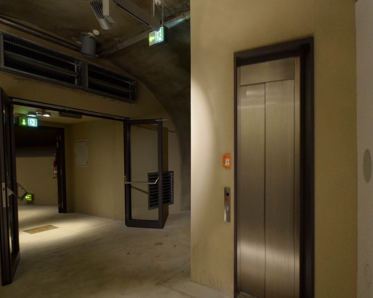
To compensate for these deficits, the tunnel was equipped with fire seals, the lift was designed as a firefighters' lift, and dynamic escape routing was put in place.
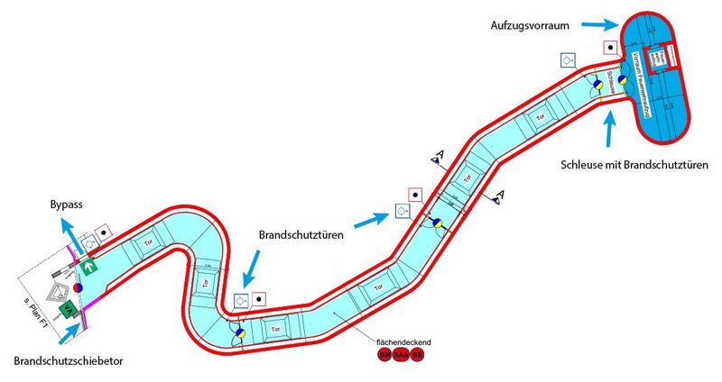
The tunnel is split into three sections with two fire seals, and separated from the area in front of the lift by a lock system. The firefighters' lift gives the fire service access to the tunnel from the castle in an emergency. To ensure the functional reliability of the firefighters' lift, a protective smoke pressure system was provided in the lift shaft and the area in front of it. The dynamic escape routing system – comprising dynamic emergency exit luminaires at head height and low-location dynamic arrows – indicate the escape route to be used in each case. The lights flash to attract increased attention. A fire alarm system that monitors the entire area controls the dynamic escape routing.
If evacuation of the tunnel becomes necessary, and no damage has been caused to the entrance building, people are led out through the entrance into the open.
In the event of a fire in the entrance building, a sliding fireproof door at the entrance to the tunnel closes. People are guided outside through the emergency exit door in the bypass. In the event of a fire in one of the tunnel’s three fire compartments, they are guided out of the affected area by the shortest route, either through the entrance building or the bypass into the open, or through the lock into the area in front of the lift. The area in front of the lift is safe because its separation from the tunnel is fire safety-compliant and it is equipped with a smoke-control pressurisation system. People who have been guided there by the dynamic escape routing system can wait there until the fire service uses the lift to rescue them.
Conclusion
A dynamic escape routing system offers low-location way guidance through the smoke, prevents people from fleeing into a smoke-filled area and indicates the safe escape route. In the event of a fire, it increases visitors' safety and is an ideal compensatory measure.
Sources
- Kempen Krause Hartmann Ingenieurgesellschaft mbH, Düsseldorf: Brandschutzkonzept zum Bauvorhaben „Erlebnisaufzug Burg Altena
- “Technische Regeln für Arbeitsstätten: „Fluchtwege und Notausgänge, Flucht- und Rettungsplan“, ASR A2.3, August 2007