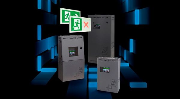
CLS Fusion
FUSION – this expression is defined as “the process or result of two or more things together to form a single entity” by the Oxford Dictionaries. This also describes our FUSION systems as we join innovative concepts and technologies to create an intelligent emergency lighting. This simplifies the usage of decentralised emergency lighting systems for the planner, installer und user.
CLS FUSION - more than just a simple concept
With the CLS FUSION we developed and optimised our decentralised systems in many ways. Not just in functional aspects, we are also setting new standards in ways of safety, connectivity and ease of use.
Functionality
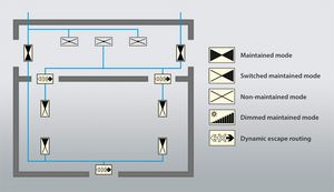
Intelligent circuits extend the mixed operation mode by more options within the same circuit.
More performance optimised luminaires can be connected to CLS FUSION due to providing up to 8 circuits. External BUS components clearly extend the functionality of the CLS FUSION.
Your Joker for the future
1998 the INOTEC Sicherheitstechnik GmbH was the first company to introduce a mixed operation mode of maintained and non-maintained lighting in one circuit under the brand name “JOKER”.
Since the launch in 2006, INOTEC CLS systems support the JOKER operation of safety and emergency exit sign luminaires in the same circuit. The CLS extended the JOKER functionality by the possibility to switch individual luminaires within a circuit via switch inputs.
With CLS FUSION it is now possible to integrate dynamic emergency exit sign luminaires into the circuit. The control is done without an additional BUS line via the existing supply line. Thereby, the planning and installation of a dynamic escape route guidance system is simplified and installation costs are reduced.
If modifications occur during the planning or usage, the static emergency exit sign luminaire can be substituted by a dynamic luminaire without new wiring!
Dynamic escape route guidance for a higher safety level
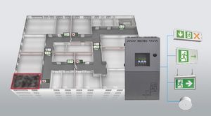
The standard emergency exit and safety lighting is designed to illuminate the escape routes and guide the way via safety signs in case of a power failure. In case of a fire, escape routes may be blocked by smoke or fire itself. A static emergency exit lighting will still display it as a safe escape route!
Dynamic escape route systems take these situations into account and block escape routes while displaying safe alternatives. They support the self-rescue of people and contribute towards the safe evacuation of buildings.
With CLS FUSION dynamic emergency exit sign luminaires are now operated without additional BUS-line in the same circuit like the standard emergency exit and safety lighting.
Flexible expansion
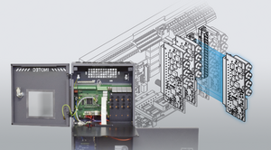
The CLS FUSION supports up to 8 circuits per device for more functionality of the emergency lighting system. The expansion can be easily done by qualified specialists on-site. Each circuit monitors and controls a maximum of 20 luminaire addresses with a maximum current of 3A.
Each luminaire can be dimmed, addressed and programmed via the new touch controller. Settings of the functionalities at the luminaire modules are not required for our CLS FUSION system.
External BUS components
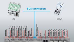
By connection of external, BUS-capable components such as light switch application (LSA) or 3-phase monitoring (DPÜ/B) modules, the functionalities of the CLS FUSION can be expanded. Especially the DPÜ/B modules enable the detailed reporting of faulty sub-dbs at the CLS FUSION controller unit and connected monitoring devices / -software.
A phase failure can be used for selective switching of individual luminaires or the triggering of dynamic escape route scenarios.
Safety
The new individual LED monitoring increases the safety level of the emergency lighting with LED luminaires compared to standard solutions. With the integrated Battery Control System (BSC) we ensure future requirements of draft standards.
Individual LED monitoring
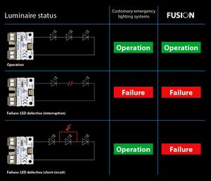
The new individual LED monitoring in our FUSION systems does not only recognise a high-impedance failure (interruption), but also the short circuit of an individual LED. Our long-term experience within the field of LED safety and emergency exit sign luminaires has shown, that a short circuit at a LED is a very common failure. More than 90% of the faulty LEDs do have a short circuit in the “LED-Chip”.
Until now this cause of failure was not identified by the luminaire monitoring and the faulty LED was not reported. The CLS FUSION technology offers the possibility to identify and report the failure.
Battery Control System (BCS)
A failure in the standby power source of the emergency lighting system can have drastic consequences. This is why the maintaining and monitoring of the standby power source is top priority for us. Most emergency lighting systems monitor several battery blocks and cannot detect a failure of an individual battery block.
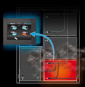
The integrated Battery-Control-System of the CLS FUSION offers more safety. It records the battery voltage as well as the temperature of every single battery block. This enables the early identification of a faulty battery block. In the worst case, a single defective battery block can destroy the other blocks in the battery set as well.
The requirements of the draft of the prEN 50171:2013 are fullfilled by the Battery-Control-System (BCS) of the CLS FUSION:
- Periodic monitoring of the battery block voltage (6.11.3. a)
- Failure message in case of a deviation of the battery block voltage (6.11.3. b)
- Only manual resetting of failure messages (6.11.3. d)
- Recording of the battery block voltage during the battery duration test with an interval of 5 minutes (6.11.3. f)
- Monitoring and recording the ambient temperature of the battery (6.11.4)
Ease of use
A modern graphical user interface simplifies the operation of the CLS FUSION. Standard interfaces like USB and network connection make it easy to read out and configure the setup.
FUSIONConnect: Cross-device transmission of switching commands for smart control of emergency luminaires
User-friendly operation
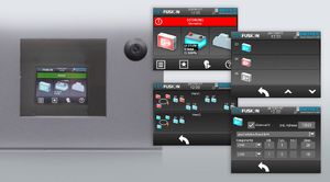
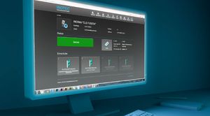
The modern, graphical user interface of the TFT touch display in our CLS FUSION system enables a user-friendly and intuitive operation.The habits of the users changed a lot due to smartphones and tablets. INOTEC takes up the concepts and simplifies the usage of your emergency lighting systems.
All status information up to luminaire level are displayed on the 3.5” TFT-touch display of the CLS FUSION.
As a result of the consistent user interface for our centralised and decentralised emergency lighting systems the user does not need to adapt to a different usage.
INOTEC Konfigurator
The installation and the commissioning works via the Windows based INOTEC Konfigurator software for all FUSION systems. The established concept of the individual operating unit address of the decentralised CLS-systems is also used for the new FUSION systems.
Connectivity
By connecting different monitoring systems like INOView, INOWeb or accessing building management systems you have full overview about the state of your decentral emergency light system in a central place.
Numerous interfaces
Thanks to the numerous interfaces on the CLS FUSION controller unit, this system offers a wide range of monitoring and programming options. Via USB-interface information can be saved on an USB-flash drive or the configuration of the system can be updated. An update of the controller software is also possible via USB-flash drive without any problems.
The integrated network interface enables the transfer of information to monitoring systems. By use of the standard feature INOWeb, information can be retrieved with any web browser via computer or mobile. All status information can be visualised up to individual luminaire failure.
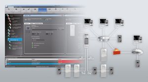
Naturally the FUSION systems can be monitored with the INOView software. Status of luminaires, BCS and attached components get displayed clearly with location text in INOView. Events are centrally recorded in the logbook for all monitored systems. For a quick localisation of the defective luminaires, they can be displayed in a floor plan with the current luminaire status.
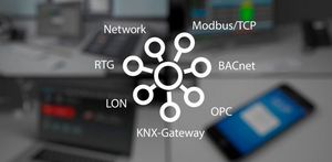
Status notifications for a building management software can be retrieved by Modbus/TCP. This way information up to luminaire level can be integrated in existing building management systems. Furthermore support for additional standard BMS protocols like OPC or BACnet is available.
INOView
INOView is the central monitoring solution for all INOTEC emergency lighting systems. This software is used, when a flexible usage is required, which grows with the project. The devices can be monitored via three-core RTG-Bus and/or a network connection.
Safety at a glance
INOView has been developed with focus on the user. Important is a simple, intuitive user operation and transparency with a clearly structured installation scheme and clear texts. The user can see the overall condition of the emergency lighting system at a glance and can take action to guarantee for the safety in the building if necessary. The INOView software helps with its transparency and offers detailed information on the system operation.
State-of-the-art client / server architecture
State-of-the-art client / server architecture means that this is a secure, future-proof investment. Multiple users on the network can access the information in the INOView software simultaneously via the clients. Integrated user administration protects the software against unauthorised access.
Powerful and easy to use
With the INOView-Software you can control your emergency lighting devices easily. Intuitive handling menus enable a simple and comfortable usage. Individual designable visualisations of the information help to increase transparency. Whether in school or at the airport, the INOView-Software meets the requirements of the customer with its modern standards.
INOWeb
TFT-touch controller with integrated INOWeb function for central monitoring of the emergency lighting device via intra-/internet. The connection works via an already existing network.
By accessing the controller’s INOWeb functionality via web browser the status of each system, circuit and luminiare can be checked on the (optionally) password-protected website. With an existing internet connection the INOWeb can be accessed from any place world-wide. Please contact your regional sales team for a demonstration.
Functions:
- Starting a function test / battery duration test
- Blocking / Releasing
- Failure printout
- Linking files / websites by circuit
It is possible to monitor complex installations with different system types at one central position with the help of the software INOWeb-Control. Therefore the TFT-touch controller needs to be integrated in an existing network.
Downloads
You can download the standard documentation for the selected device here.
The download is restricted to order numbers, which have the device included.
