GMS Help
Assembly and commissioning
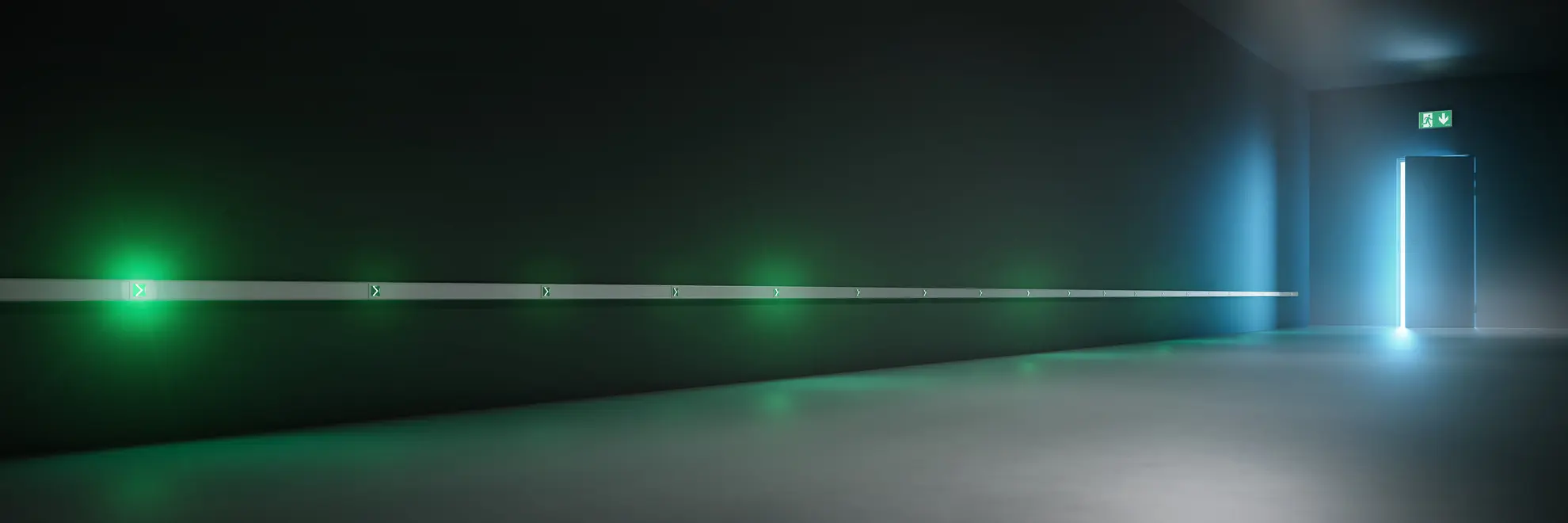


GMS trunking with GMS modules and equipment
GMS trunking and components
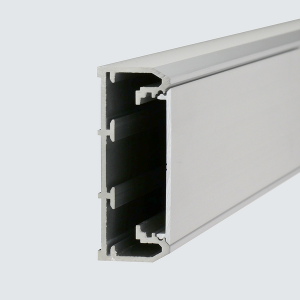
Aluminium trunking for safety guidance system GMS. Length 2,000 mm. Delivery incl. cover, 1 x length connector, 5 x cable retainer clips.
| Colour: anodised | 104598635 |
| Colour: RAL 9016 | 104636324 |
| Colour: RAL SC | 104636425 |
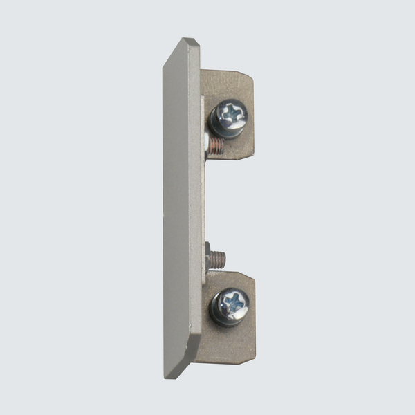
Aluminium trunking end cap for GMS safety guidance system.
| Colour: anodised | 104619550 |
| Colour: RAL 9016 | 104619651 |
| Colour: RAL SC | 101396726 |
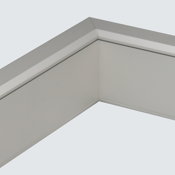
Aluminium trunking inner corner for GMS safety guidance system.
| Colour: anodised | 104640768 |
| Colour: RAL 9016 | 104640869 |
| Colour: RAL SC | 104641172 |
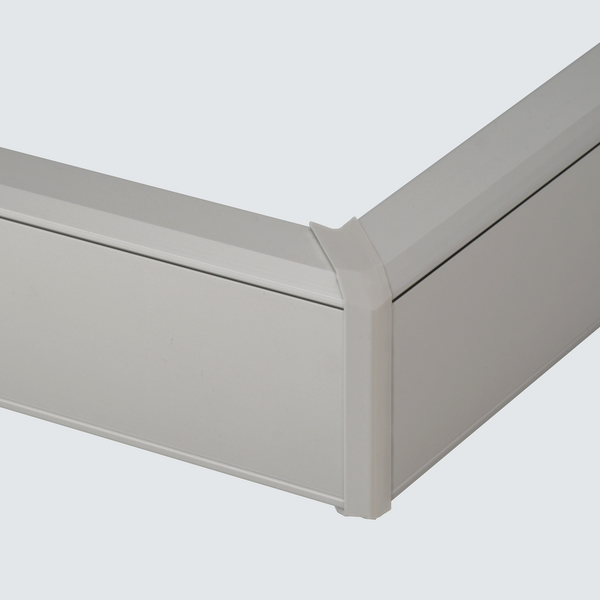
Aluminium trunking outer corner for GMS safety guidance system.
| Colour: anodised | 104640970 |
| Colour: RAL 9016 | 104641071 |
| Colour: RAL SC | 104641273 |
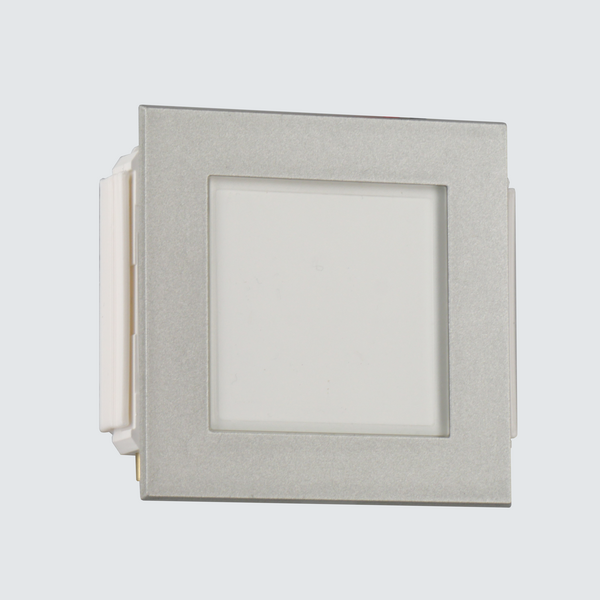
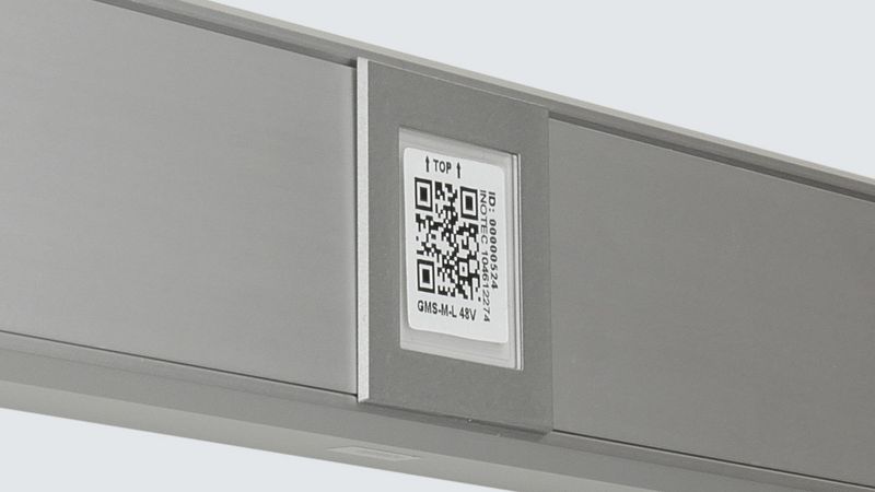
GMS light marker GMS-M-L module for direction indication. For installation in GMS aluminium trunking. Control and supply via GMS controller (GMS-C).
| Colour: anodised | 104612274 |
| Colour: RAL 9016 | 104619348 |
| Colour: RAL SC | 104619449 |
GMS assembly
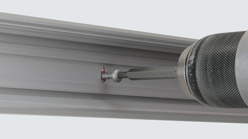
Installing the trunking
Install the GMS trunking on the wall. The longitudinal connector supplied helps with the clean and quick installation of additional trunking sections. Note: According to the preliminary standard DIN VDE V 0108-200 "Safety lighting systems - Part 200: Electrically operated optical safety guidance systems", a safety guidance system close to the floor should be mounted a maximum of 40 cm above the floor.
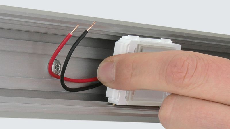
Insert GMS-M...
The GMS modules are simply clipped into the GMS trunking at the desired position using the spring assembly. Note: According to the preliminary standard DIN VDE V 0108-200 "Safety lighting systems - Part 200: Electrically operated optical safety guidance systems", the maximum distance between two light markers should be 1.5 metres. We recommend a maximum distance of 0.8 m for a running light function.
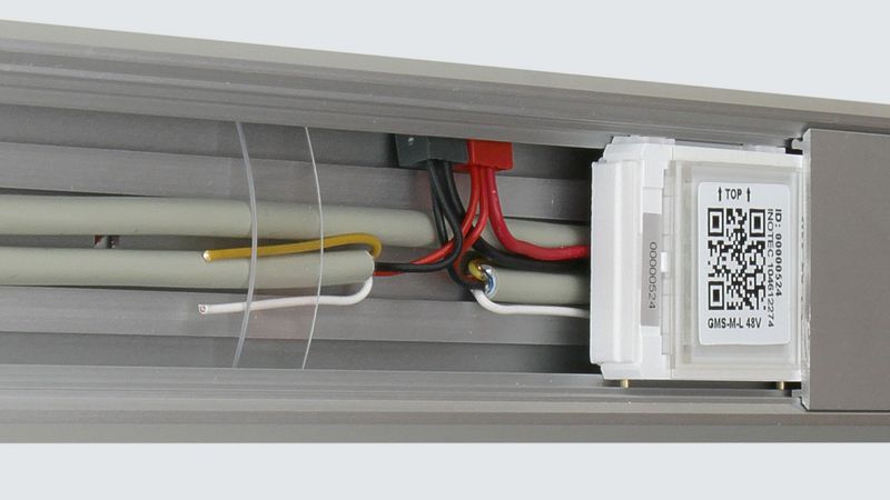
Create wiring in the GMS trunking
Wiring is carried out with J-Y(St)Y 2 x 2 x 0.8. For a fast connection, we recommend MICRO connection terminals (e.g. Wago series 243). Optimum redundancy is achieved by alternating the wiring of the GMS modules on two lines.
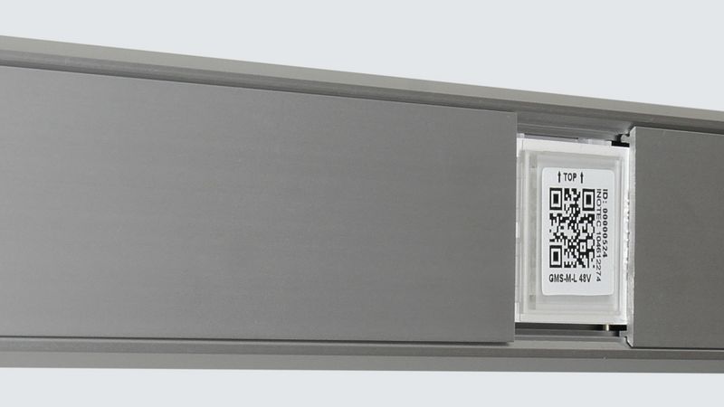
Mounting the cover
Mount the GMS trunking cover. To ensure that the cover frame fits perfectly, the distance between the covers should be 40 mm.
Mounting the cover frame
The cover frame can now be mounted.
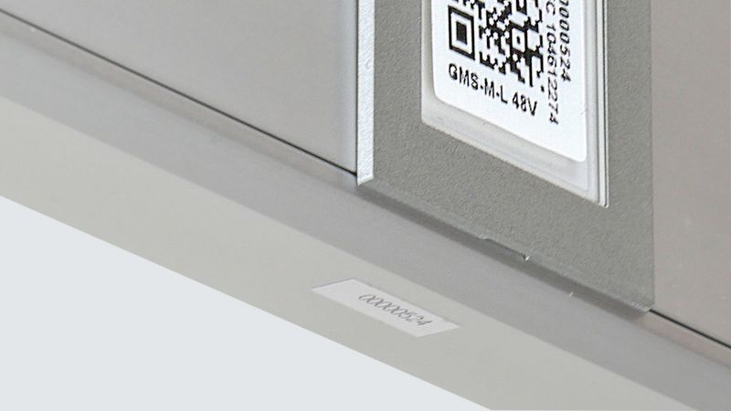
Stick address label under the profile (hint)
To make it easy to find the address of the GMS module in the event of maintenance or a defect, we recommend sticking one of the enclosed address stickers under the GMS trunking from below. This makes it easy to read the address even after installation.

Remove the label on the light outlet
After successful installation and setup, the label on the GMS module can be removed.
GMS controller and GMS power supply
GMS controller – Components
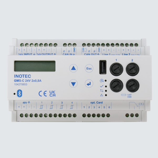
GMS controller for controlling and supplying GMS light marker modules in the GMS safety guidance system.
| GMS-C 230 V 2 x 1 A | 104228015 |
| GMS-C 24 V 2 x 0,8 A | 104270653 |
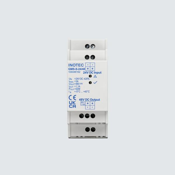
48 V power supply for GMS-Controller.
| GMS-S-230 / 48 Power Supply, 230 V / 48 V 2,1 A | 104641374 |
| GMS-S-24 / 48 Power Supply, 24 V / 48 V 1,1 A | 104446162 |
GMS controller – Connection

GMS-C 24 V to CLS FUSION
- Max. 20 light markers per line
- Max. 40 light markers per controller
- Cable length to GMS-C: max. 10 m
- Cable length for lines 1 and 2: max. 250 m
- Use a separate terminal block
- Do not mix with emergency lights on a single terminal block
Current draw CLS FUSION
| Number | Current |
| 10 × GMS-M light markers | 0.8 A |
| 20 × GMS-M light markers | 1.3 A |
| 30 × GMS-M light markers | 1.8 A |
| 40 × GMS-M light markers | 2.3 A |
GMS-C 230 V to CPS FUSION
- Max. 40 light markers per line
- Max. 80 light markers per controller
- These values apply when calculating the circuit load
- Values 50 to 80 refer to both lines combined
Current consumption on the 230 V circuit
| Number | Current |
| 10 × GMS-M light markers | 0.13 A |
| 20 × GMS-M light markers | 0.21 A |
| 30 × GMS-M light markers | 0.30 A |
| 40 × GMS-M light markers | 0.38 A |
| 50 × GMS-M light markers | 0.45 A |
| 60 × GMS-M light markers | 0.53 A |
| 70 × GMS-M light markers | 0.61 A |
| 80 × GMS-M light markers | 0.68 A |
Simplified planning:
1 emergency light / emergency exit sign = 2 light markers
Note: Plan the 24 V and 230 V system variants separately.
INOTEC app for configuration
Programming CLS FUSION
After the hardware installation, the GMS-C must be programmed in the CLS FUSION. This can be done via the Configurator or the control unit.
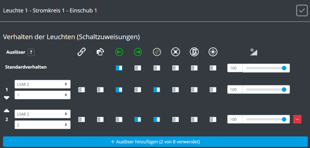
Programming in the Configurator
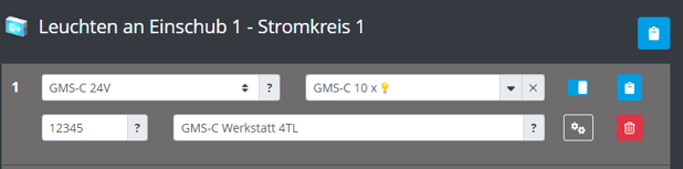
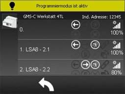
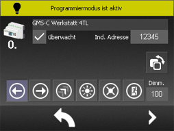
Programming on the control unit
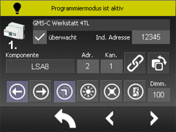
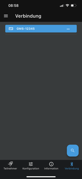
INOTEC App
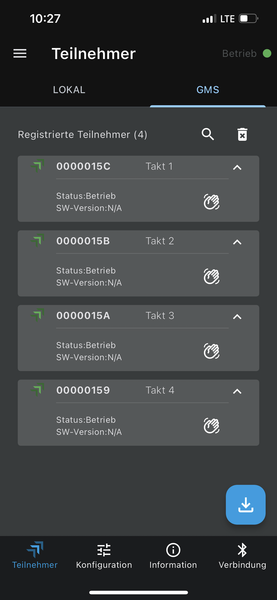
The INOTEC app can be used to capture the GMS modules, transfer them to the GMS-C and configure them.
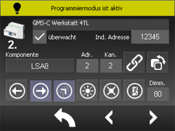
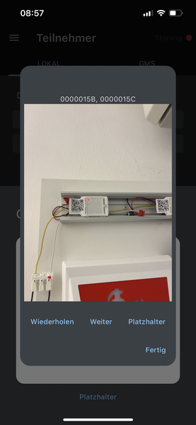
Register participants 1
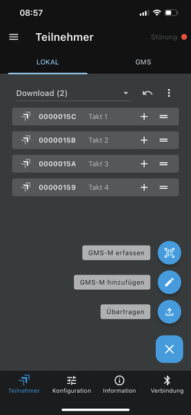
Register participants 2
Configure light markers
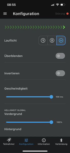
- All settings are displayed as a preview in real time
- Chaser: The following patterns are available here: 4 bars, 8 bars and flying field
- Fade: The upstream and downstream arrows are dimmed. This function provides a quieter running light
- Invert: Reverses the direction of the running light
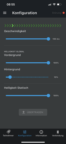
- Speed: Controls the speed of the chaser
- Foreground brightness: Controls the brightness of the active light markers
- Background brightness: Controls the overall brightness of all non-active light markers
- Static brightness: Settings for the static light markers
- Transfer: After configuration, the settings must be transferred to the GMS-C
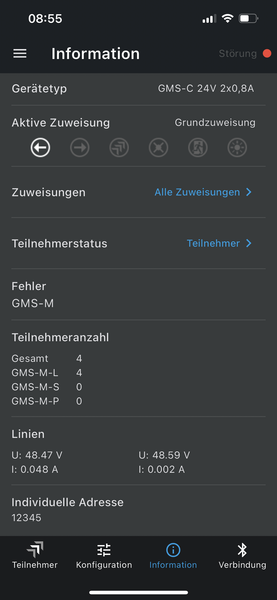
Information and Settings

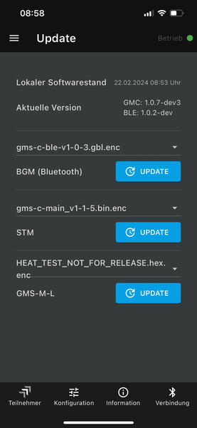
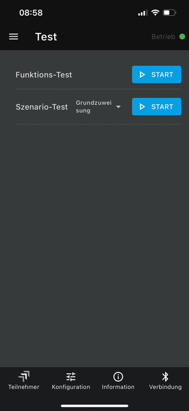
Update and Test